RailRider Pro®
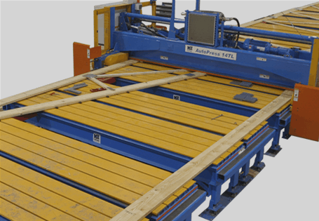
Floor Truss Press
A top choice year after year for manufacturing floor trusses.
Features
Efficient floor truss assembly
- The table comes in multiple lengths, all with gantry head parking areas.
- Pneumatic clamp has automatic depth adjustment for jigging two trusses.
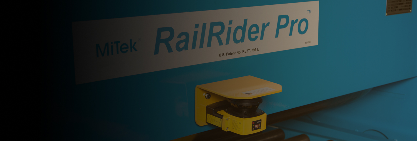
- Scanners on each side of the press head keep employees safe while also preventing equipment damage.
- Lots of options for even more efficiency!
RailRider Pro Overview Video
Specifications
The press, designed specifically for floor truss assembly, accomplishes 100% plate embedment on each pass.
- The 40′ table features 42′ of jigging space and comes equipped with gantry head parking areas on both ends
- A radio-controlled remote allows pneumatic jigging operation from a distance
- Various ejection methods are available to quickly transition to the next truss
- See all the options available on the Options page.
- Place boards on the infeed side of the table in the correct configuration.
- Use the radio-controlled remote to activate pneumatic cylinders that clamp the boards together. The clamp automatically adjusts for the truss width.
- Place connector plates on the face-up side of the truss.
- Using the pendant controls, roll the gantry head over the truss to completely embed the plates.
- Flip the truss from the infeed side to the outfeed side using the optional pneumatic pop-ups or flippers controlled by the remote, or by hand if optional pneumatics are not installed.
- Assemble another press on the infeed side of the table while simultaneously placing plates on the face-up side of the truss that is on the outfeed side of the table.
- Roll the gantry head over the trusses to completely embed the plates. Once the process is started, a completed truss comes off the table on every pass of the gantry head.
- If the on-table splicing is installed, spliced lumber can also be built with every roller pass.
- For end-eject systems, pivot the flip-stop on the end eject end of the outfeed side so there are no tools needed to remove jigging before ejecting the truss.
- Remove the truss from the outfeed side using the ejection options controlled by the remote, or by hand if optional pneumatics are not installed.
- Repeat process starting with step #5.
PHYSICAL DATA
| Dimensions of Gantry | 10′ 3″ wide w/platform |
| Roller Size | 24″ nominal OD |
| Roller Material | 1″ steel |
| Throat Opening | 7′ 4″ wide, covers both sides of table |
PERFORMANCE DATA
| Speed of travel | 100 FPM (see Options) |
| Lumber capacity | Trusses 9-1/2″ to 24″ wide (see Options) |
| Direction of travel | Left and right |
| HMI | Pendant for gantry head controls and radio-controlled remote for pneumatic controls |
ELECTRICAL DATA
| Electrical Specs | 208 / 230 / 460 / 575 VAC, 60 Hz, 3-phase |
| Uses overhead bus bar or festoon cable |
- On-table splicing: Splicing extensions allow you to lay boards end-to-end so they are spliced together at the same time the roller is pressing the truss.
- Overhead plate rack: Drastically reduce non-value-added motion by storing multiple plate sizes above the table surface, right at the assemblers fingertips.
- Increase the truss width capabilities to:
- 11-7/8″ to 26″ or
- 12″ to 30″
- Dual pneumatic zones to build and eject two shorter trusses instead of one long truss
- Pendant on opposite side of operation
- Customized camber on side rail
- Powered conveyor for end eject systems
- Pneumatic options:
- Flipper on infeed side
- Pop-ups on infeed and/or outfeed side
- Side-eject lifters on outfeed side
- End-eject lifters on outfeed side

Download the Full Spec Sheet
Download PDFAutomation SUPPORT & RESOURCES
MiTek offers consulting, testing, documentation, design assistance and prompt customer service. Visit our Support, Training and Knowledge Base center for more information.
RELATED EQUIPMENT
View more of the most complete, reliable, and productive truss assembly manufacturing equipment in the industry.
